Wiring

Home

Downloads
Train Shows
Local Model RR Clubs
Local Hobby Shops
Texas RR Attractions
RR Radio Frequencies
Live Rail Video
Internet Train Stores
Manufacturer's Links
RR Search Engines
Virtual Train Tours
Model Video Cameras
Coffee Table Layouts
Trains smaller than Z
Prototypical Operation
You're The Engineer
Railroad Quiz
Contact Me
Talk About Trains
Railroad Webrings
High Speed Rail
Computer Software
History of Railroads
Locomotives
Prototype Photos
Model RR History
Photos of Models
Your Own Web Site
Pages To Be Added
DFW Trains

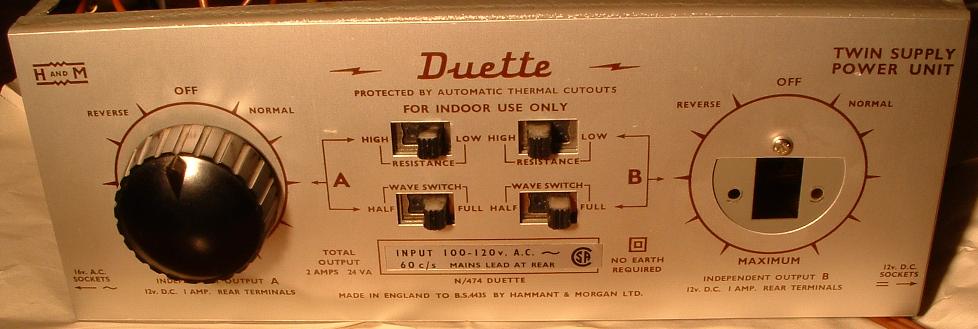
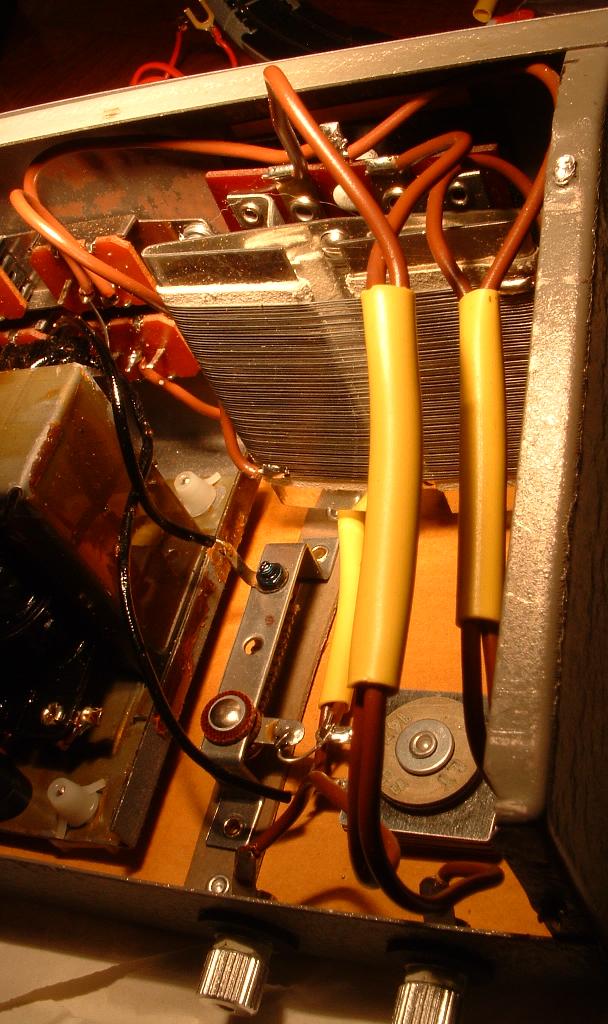
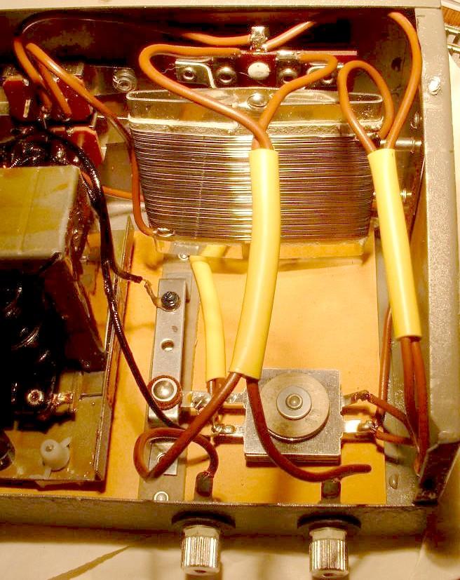
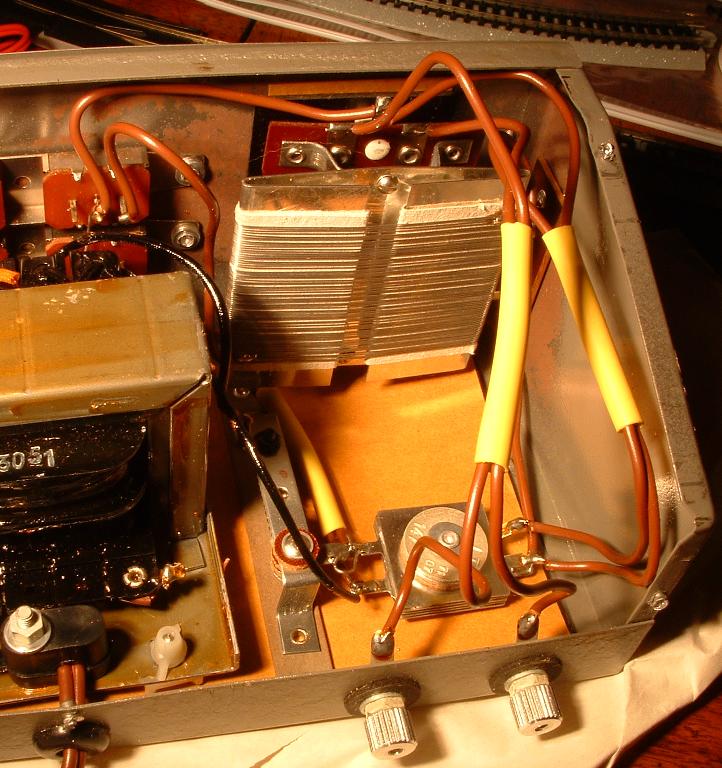
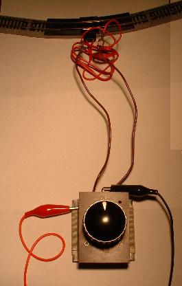
Below on this page are photos of a model train power pack made in England that has two totally separate rheostats (wired independently) to control two model train engines.
 
The rheostats are unique in that they are what I call "bidirectional rheostats" meaning that they can be rotate either clockwise (as rheostats usually are) or these can be rotated counterclockwise.  (There is a middle "OFF" position ("12 o'clock") where the power is not sent to the track.) 
 
The effect is that when the rheostat is rotated clockwise, the model train engine moves forward (left-to-right).  When the bi-directional rheostat is rotated counterclockwise, the model train engine moves backward (right-to-left).
 
The advantage of this is that no "reversing switch" (D.P.D.T.) is needed to reverse the train's direction which means that operation is simpler, easier, and more intuitive for new users.
 
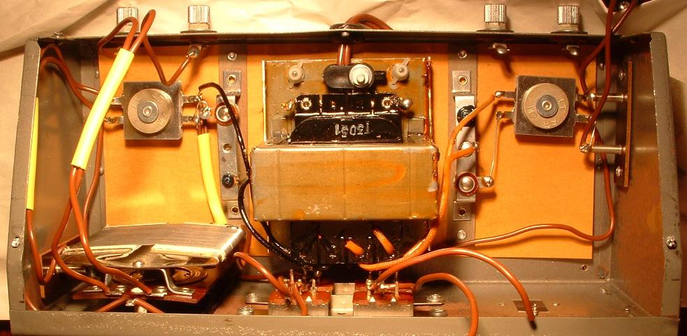
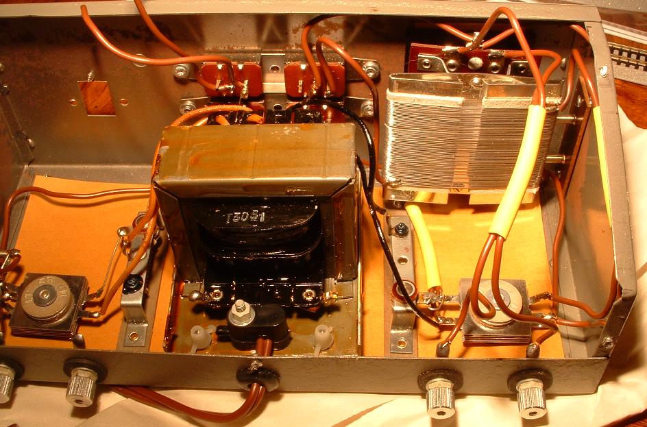
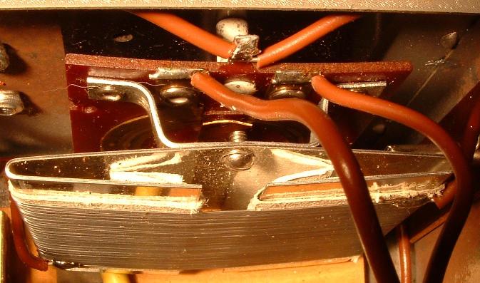
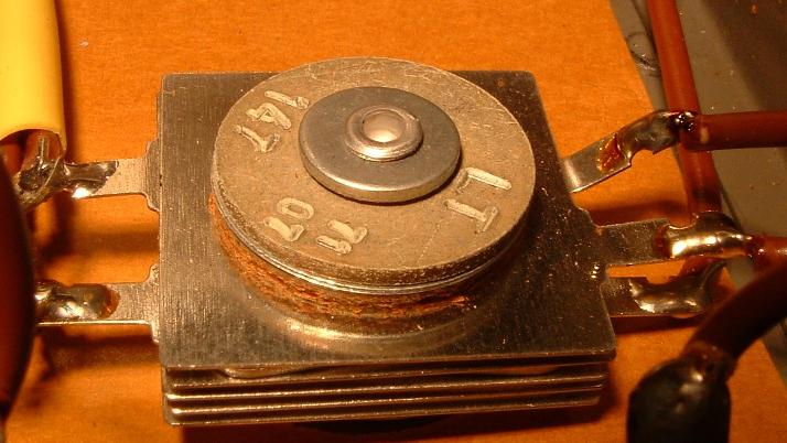
This power pack also uses pulse power which it calls "Half Wave" (which at the moment I am not interested in using).  It also uses a selinum rectifer to allow the user to have more precise control over the movement of the engine which I am very interested in using.  (By the way, there are two complete systems inside this power pack - i.e. two separate rectifiers, two separate bi-directional rheostats, etc.)
 
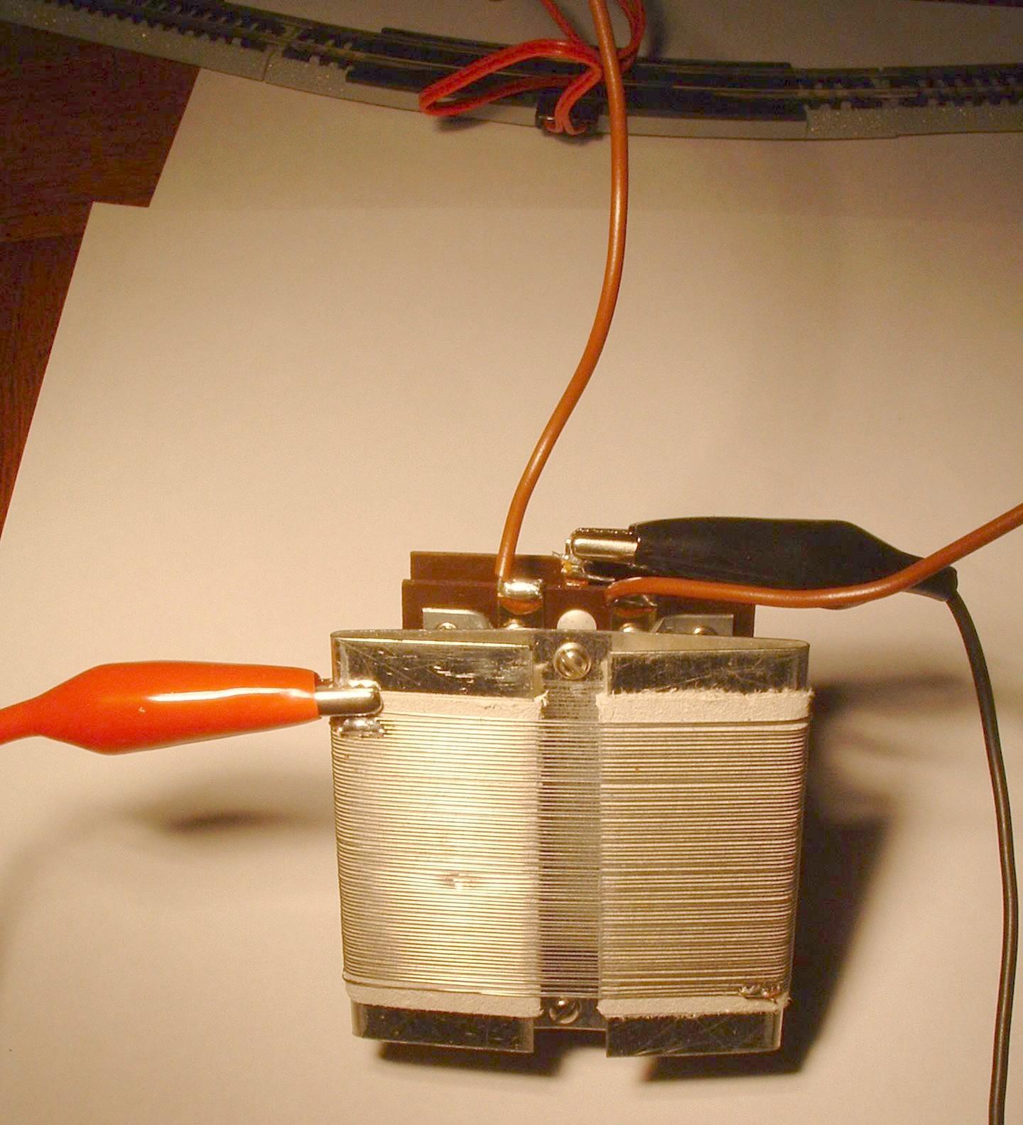
I have removed the rheostat from the right side of the power pack.  I plan to remove both rheostats and use them by themselves (without the transformer in the power pack.  I will power them with two separate power supplies.)  I do not plan to use the transformer that came with the power pack.
 
However, I would like to use the selinum rectifiers that came inside the power pack.
 
Here are the photos:
 

1_front.jpg

2_top.jpg

3_back.jpg

4_bidirectional_rheostat.jpg

5_wiring_photo_1.jpg

6_wiring_photo_2.jpg

7_selenium_rectifier.jpg

8_closeup_of_rectifier.jpg

.

Shown below are two photos of the bi-directional rheostat that was removed from the model train power pack.  The alegator clips are connected to a separate 12 volt power supply (a Radio Shack plug-in unit formerly used to power answering machines, portable cassette recorders, etc.)
 
The two wires that are show soldered to the rheostat are connected to the model train track. 
 
At first, this rheostat was wired exactly like the one still inside the power pack.  Ironically though, that did not work (trains only reacted on one-half of the rheostat when wired exactly like the one inside the power pack).  So, trial-and-error was used to figure out the wiring connection that would cause the bi-directional rheostat to be able to control the model train engine correctly in either direction (depending on which direction the rheostat was rotated).
 

101.jpg

So now I want to remove the selenium rectifier from the power pack (shown in the photos above) and include it in the circuit with the bi-directional rheostat I have removed from the power pack.  (I tested the rheostat still inside the power pack and the selenium rectifier connected to it seems to allow the user to have more precise control over the movement of the model train engine.) 
 
[NOTE:  The slide switch on the front of the power pack that controls whether the selenium rectifier is included in the circuit of the power pack or not is labeled, "Resistance".  (See first photo at top of page.)]
 
So, refering to the rheostat I have removed from the power pack and am using outside the power pack, the question is:
 
1 - Where in that circuit do I include the rectifier?
 
2 - Since there are five connections on the rectifier, which two do I use?


102.jpg

.